For utility-scale solar engineering, two tools sit at the core of every serious project delivery pipeline: PVcase Ground Mount for terrain-adaptive layout and electrical design inside AutoCAD, and PVsyst for bankable energy yield simulation. Neither tool replaces the other — they are complementary by design. PVcase does what PVsyst cannot: physical site layout, terrain grading, cable routing, and construction documentation. PVsyst does what PVcase cannot: rigorous energy modeling, loss analysis, and the P50/P90 yield reports that lenders require before approving project financing.
The quality of the connection between these two tools determines how much time your team wastes — or saves — on every project cycle. A poorly managed handoff means manually rebuilding shading scenes in PVsyst, disconnected versions between the CAD layout and the energy model, and hours of rework on every design iteration. A well-managed handoff means a round-trip from layout change to updated energy model in minutes, with full terrain accuracy preserved throughout.
This guide covers the complete workflow from terrain import in PVcase through to a finished bankable PVsyst report — including the technical details of export formats, PVsyst orientation management, tracker backtracking setup, and the most common errors engineers encounter at the handoff point.
Understanding the Role of Each Tool
Before diving into the workflow, it helps to be precise about what each tool contributes and where its responsibility ends.
PVcase Ground Mount is responsible for everything that happens on the physical site: importing terrain data, defining site boundaries and exclusion zones, placing panel rows (fixed-tilt or tracker), adapting row geometry to ground slope, routing DC cables, sizing strings, and producing construction drawings. PVcase does not simulate energy yield — it is an engineering design tool, not a simulation engine.
PVsyst is responsible for everything that happens in the energy model: taking the physical layout as input, applying weather data, modeling irradiance, shading losses, temperature coefficients, inverter efficiency curves, wiring losses, soiling, degradation, and all other energy loss pathways. The output is a complete loss tree and an annual energy yield figure, expressed probabilistically as P50 (the median expected output) and P90 (the conservative figure that the plant has a 90% probability of exceeding). P90 is the number banks use to size debt.
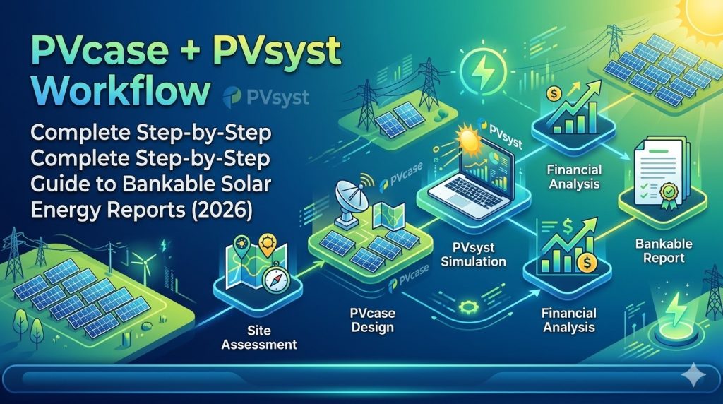
The workflow between them is linear but iterative: you design in PVcase, export to PVsyst, run the simulation, evaluate the results, return to PVcase to adjust the layout if needed, re-export, and re-run. Getting this loop fast and lossless is the entire point of the integration.
Phase 1 — Site Preparation and Terrain Import in PVcase
Step 1.1 — Import Terrain Data
Open PVcase Ground Mount inside AutoCAD. Your first task is to bring real site topography into the workspace. PVcase accepts terrain in several formats:
- DWG / DXF — standard AutoCAD terrain files with elevation contours or 3D mesh data
- Point cloud files — from LIDAR surveys or drone photogrammetry
- Shapefiles (.shp) — GIS boundary and terrain data, after coordinate system alignment
Import your terrain file using the PVcase terrain import function. Once loaded, PVcase processes the elevation data and generates a 3D mesh of the site surface. This mesh is the foundation for everything that follows — all row placement will be adapted to this geometry.
If your terrain data comes from an external survey in a local coordinate system, align it to the AutoCAD workspace coordinate system before proceeding. Coordinate system misalignment is one of the most common causes of problems at the PVsyst export stage.
Step 1.2 — Define Site Boundaries and Exclusion Zones
Using PVcase’s boundary tools, define the outer perimeter of the buildable area. Then mark any internal exclusion zones: access roads, substation areas, wetland buffers, slope-limit exclusions, and setback requirements from property lines. PVcase will respect these boundaries during automated layout generation.
Step 1.3 — Configure Module and Mounting Parameters
Set up your panel parameters in PVcase — module dimensions, power class, and mounting configuration (fixed-tilt or single-axis tracker). For fixed-tilt systems, define tilt angle, azimuth, and target row pitch or Ground Coverage Ratio (GCR). For tracker systems, define axis azimuth, maximum rotation angle, and pitch.
These parameters matter at the PVsyst stage too — PVcase will carry them into the export file, so setting them correctly here prevents manual re-entry in PVsyst.
Phase 2 — Layout Generation and Electrical Design
Step 2.1 — Generate Terrain-Adaptive Layout
Run PVcase’s automated layout generation. The software places panel rows across the site, adapting each row’s position and height to the terrain mesh. On sloped sites, PVcase adjusts row geometry to maintain target pitch distances along the actual ground surface — not projected horizontal distances, which would be incorrect on significant slopes.
Review the generated layout against your design targets: total DC capacity, GCR, number of strings, and slope compliance. Use PVcase’s multi-scenario comparison tool to evaluate alternative configurations — varying tilt angle, pitch, or GCR — before committing to a final design.
Step 2.2 — Shading Analysis
Run PVcase’s inter-row shading analysis for your geographic location. PVcase calculates shading losses for the full annual sun path, accounting for the actual terrain geometry of your layout. This data becomes the shading scene exported to PVsyst — so the accuracy of this calculation directly affects the accuracy of your final energy yield report.
Step 2.3 — Electrical Design and String Layout
Define string groupings and run PVcase’s DC cable routing module. The software calculates optimal cable paths across the layout, minimizing total cable length while respecting voltage and current limits. It generates a bill of materials for DC cables that can go directly to procurement.
Record the key electrical parameters: total number of modules, strings per inverter block, DC system voltage, and inverter type. You will need these when configuring the PVsyst system in Phase 3.
Phase 3 — Exporting from PVcase to PVsyst
This is the critical handoff. PVcase supports two export formats for PVsyst, and choosing the right one matters.
Export Format Options
.PVC format — This is the recommended format for PVsyst 7.0 and higher (including PVsyst 8). It is a structured file that carries frame geometry, shading objects, terrain data (when selected), and orientation parameters. PVsyst can read module-level and group-level frame definitions from a .PVC file, and for tracker layouts, it automatically identifies the axis plane and rotation angle range from the PVcase data.
.DAE format — A legacy 3D geometry format. Still supported but less efficient than .PVC for current PVsyst versions. Use .PVC unless you have a specific reason to use .DAE.
Step 3.1 — Generate the Terrain Mesh
Before exporting, if you want to include terrain in the PVsyst shading scene — which is recommended for any site with significant topography — you must first generate a terrain mesh in PVcase. In the PVcase ribbon, use the terrain mesh generation function. Note that mesh density affects both file size and PVsyst import speed: a finer mesh gives more accurate terrain shading but takes longer to process in PVsyst. Calibrate mesh density to your site complexity.
Step 3.2 — Run the Export
In the PVcase top ribbon, click Export to PVsyst. You will see two options:
- Frames only — exports panel frames and shading objects, without terrain. Use this for flat sites where terrain shading contribution is negligible.
- Terrain and Frames — exports panel frames, shading objects, and the terrain mesh as a CSV file. Use this for any site with meaningful topography. This option only appears if a terrain mesh has already been generated.
Select your export option, choose .PVC as the file format, name the file, and save it to your project folder. PVcase will produce the .PVC file (frames and shading objects) and, if you selected terrain export, a separate .CSV file for the terrain mesh.
Step 3.3 — Tracker-Specific Export Notes
For single-axis tracker layouts, PVcase automatically encodes tracker axis orientation, pitch, and maximum rotation angle into the .PVC file. When imported into PVsyst, the software reads these parameters directly — you do not need to re-enter tracker geometry manually. After import, navigate to Tools → Backtracking Management in PVsyst and verify that the pitch distance matches your PVcase design. Enable backtracking if your tracker system supports it — this is especially important for terrain-following tracker layouts where row-to-row shading on irregular ground would otherwise cause significant mismatch losses.
Phase 4 — Importing into PVsyst and Building the Simulation
Step 4.1 — Create a New Project in PVsyst
Open PVsyst and create a new grid-connected project. Set the site location — use coordinates that match your PVcase project. Import meteorological data from your preferred source (Meteonorm, SolarAnywhere, NASA POWER, or a site-measured dataset). For bankable reports, using two independent meteorological datasets and cross-validating them is standard practice and reduces the uncertainty range on your P90 estimate.
Step 4.2 — Import the PVcase .PVC File
Navigate to the Near Shadings section in PVsyst. Select Import → PVC file and load the file exported from PVcase. PVsyst will display an import results window confirming the number of frames, shading objects, and orientation groups detected.
Important: Coordinate translation. If you included terrain in the export, you must uncheck the Automatic Translation box in the import dialog and set x=0, y=0, z=0 manually. If you leave automatic translation enabled when importing the terrain CSV separately, the terrain mesh and the frame layout will appear shifted relative to each other — a common error that produces incorrect shading calculations.
Step 4.3 — Import Terrain CSV (if applicable)
After importing the .PVC file, go to File → Import → Ground data (CSV) to load the terrain mesh. With the coordinate translation set to zero as described above, the terrain will align correctly with the frame layout. Once imported, right-click on the terrain object in the shading scene and enable Shadow casting if you want PVsyst to account for terrain self-shading during simulation. Be aware that enabling shadow casting for terrain significantly increases simulation calculation time — evaluate whether this is warranted for your site’s topography.
Step 4.4 — Manage Orientations
PVsyst automatically attempts to identify frame orientations by grouping similar fields. On terrain-following layouts — where individual rows are tilted at slightly different angles because they follow the ground slope — PVsyst may detect too many distinct orientations and generate a warning.
When this happens, do not click Update Orientation Parameters. Instead, navigate to Tools → Orientation Management in the 3D scene and either increase the grouping tolerance or delete all auto-detected orientations and manually assign all frames to a single unified orientation. PVsyst retains the individual frame tilt properties in its internal calculations even when showing a single consolidated orientation in the report — so grouping for display purposes does not reduce accuracy.
After resolving orientation grouping, check whether PVsyst shows a warning about orientation mismatch between the collector plane defined in System settings and the imported shading scene. If this appears, verify that your module dimensions and tilt angle in PVsyst’s System section match the PVcase frame configuration. Use PVcase’s Frame Information function to confirm the exact values if needed.
Step 4.5 — Configure System Parameters in PVsyst
With the shading scene confirmed, configure the system in PVsyst’s System section:
- Select the PV module from the PVsyst database — match manufacturer, model, and power class to your PVcase module selection
- Configure inverter selection and number of inverter units
- Enter the stringing configuration: modules per string, strings per inverter input
- Verify that the total system DC capacity matches your PVcase layout output
For tracker systems, confirm that the tracker parameters in PVsyst’s System section — axis azimuth, maximum rotation angle, and backtracking settings — match the PVcase design.
Step 4.6 — Configure Loss Parameters
For a bankable report, loss parameters must be justified and documented. Standard loss categories in PVsyst include:
- Soiling losses — site-specific, typically 1–3% annually in dry climates, higher in desert regions
- Module quality / LID — Light-Induced Degradation, typically 0.5–2% depending on module technology
- Mismatch losses — typically 0.5–1% for well-matched strings
- Wiring / ohmic losses — typically 0.5–1.5% DC side; should be informed by your PVcase cable routing design
- Unavailability — planned and unplanned downtime, typically 0.5–1%
- Annual degradation — module efficiency decline over project lifetime, typically 0.5% per year for monocrystalline
Each assumption should be referenced to manufacturer data, site studies, or industry standards. Independent Engineers reviewing the report for project financing will scrutinize these inputs.
Phase 5 — Running the Simulation and Generating the Bankable Report
Step 5.1 — Run the Simulation
With all parameters configured, run the PVsyst simulation. For the first run, review the loss tree carefully. Check that individual loss categories fall within expected ranges — anomalies here often point to a configuration error rather than a site characteristic. Common first-run issues include unexpectedly high near-shading losses (which may indicate a geometry import problem) or DC wiring losses that don’t match the cable lengths from PVcase.
Step 5.2 — P50/P90 Yield Analysis
Once the base simulation is satisfactory, run the P50/P90 probabilistic analysis. PVsyst generates these estimates using a Gaussian uncertainty model that accounts for:
- Interannual variability in solar resource (derived from the meteorological dataset’s statistical spread)
- Modeling uncertainty in the simulation itself
- Measurement uncertainty in the weather data source
P50 is the median expected annual output — a 50% probability of being exceeded in any given year. P90 is the conservative figure — a 90% probability of exceedance. Lenders and debt financiers typically size project debt based on P90 to protect debt service coverage ratios against underperformance years. A tighter gap between P50 and P90 — achieved through high-quality meteorological data and well-documented loss assumptions — means a higher P90 relative to P50, which translates directly into more borrowable debt at lower interest rates.
Step 5.3 — Generate and Review the Report
Generate the PVsyst report. A complete bankable energy report should include:
- System description with array configuration, inverter selection, and orientation parameters
- Meteorological data source documentation
- 3D shading scene with near-shading loss table
- Complete loss tree (Sankey diagram) with all loss categories itemized
- Monthly energy yield projection
- Annual P50 and P90 estimates with full uncertainty decomposition
- Module and inverter specification sheets from the PVsyst component database
Review the report against your project’s technical due diligence requirements before submission to lenders or independent engineers.
Phase 6 — Design Iteration
Rarely does the first simulation produce a final result without at least one layout adjustment. Common iteration triggers include:
- Near-shading losses higher than target — reduce GCR or increase row pitch in PVcase
- DC capacity below target — add rows to underutilized areas of the site
- Inverter loading ratio outside optimal range — adjust string count or inverter selection
- Lender feedback requesting sensitivity runs at different tilt angles or GCR values
The iteration cycle is: adjust layout in PVcase → re-export .PVC → re-import in PVsyst → re-run simulation. Because PVcase exports the complete shading geometry automatically, this cycle takes minutes rather than the hours it would require if you were rebuilding shading scenes manually. On a real project with multiple design rounds, this time saving compounds across the project timeline.
Version control note: Maintain a consistent naming convention for your PVcase DWG files and PVsyst project files across iterations (e.g., ProjectName_v01_PVcase.dwg / ProjectName_v01_PVsyst.prj). On projects with multiple design versions, a mismatch between the CAD layout version and the PVsyst project version used in a report is a common and costly error.
Common Errors and How to Fix Them
Terrain and Layout Appear Shifted in PVsyst
Cause: The Automatic Translation box was left checked when importing the terrain CSV, causing a coordinate offset between the terrain and the frame layout.
Fix: Re-import both files. When the import dialog appears, uncheck Automatic Translation and manually set x=0, y=0, z=0 before confirming the import.
Too Many Orientations Warning in PVsyst
Cause: Terrain-following row placement creates slight variations in individual row tilt angles, which PVsyst interprets as separate orientations.
Fix: Navigate to Tools → Orientation Management in the PVsyst 3D scene. Either increase the grouping tolerance or delete all auto-detected orientations and reassign all frames to a single unified orientation manually.
Orientation Mismatch Warning
Cause: Module dimensions or tilt angle in PVsyst’s System settings don’t match the imported shading scene from PVcase.
Fix: Use PVcase’s Frame Information function to confirm the exact module dimensions and tilt used in the design. Update PVsyst’s System settings to match. If you changed module size or power in PVcase after initial frame creation, regenerate the frame area or apply Swap Preset in PVcase before re-exporting.
Unexpectedly High Near-Shading Losses
Cause: Usually indicates a geometry import problem — frames may be positioned incorrectly relative to each other in the PVsyst scene.
Fix: Open the 3D shading scene in PVsyst and visually inspect the layout. Check that row spacing in the 3D scene matches your PVcase design parameters. If frames appear stacked or misaligned, re-export from PVcase and re-import.
Tracker Backtracking Not Activating
Cause: Backtracking is not enabled in PVsyst’s Backtracking Management, or the pitch distance entered in PVsyst doesn’t match the PVcase design.
Fix: In PVsyst, navigate to Tools → Backtracking Management after importing the tracker layout. Verify the pitch distance. Enable backtracking and confirm the axis tilt range matches your tracker system specification.
Bifacial Module Considerations
PVcase handles the physical layout and electrical design of bifacial module arrays identically to monofacial — the frame geometry is the same. The bifacial gain modeling happens entirely in PVsyst. When your layout uses bifacial modules:
- Select a bifacial module from the PVsyst component database and configure the bifaciality factor (typically 0.65–0.75 for standard bifacial products)
- Configure the albedo value for your site surface — this directly affects rear-side irradiance and bifacial gain
- PVsyst’s terrain model, when imported from PVcase, contributes to more accurate rear-side irradiance calculations by capturing ground shading patterns
What the Combined Workflow Delivers
When PVcase and PVsyst are connected correctly, the combined workflow produces a complete engineering and financial package for a utility-scale solar project:
- From PVcase: Construction drawings (DWG), terrain-adapted layout, electrical design, DC cable BOM, pile placement plan
- From PVsyst: Bankable energy yield report, P50/P90 estimates, loss tree, monthly generation profile, financial model inputs
These two outputs together satisfy the requirements of EPC contractors, permit authorities, technical independent engineers, and project lenders — covering the full scope from construction through project financing.
Frequently Asked Questions
Does PVcase replace PVsyst entirely?
No. PVcase handles physical layout and engineering documentation. PVsyst handles energy simulation and produces the bankable yield reports that lenders require. They are complementary tools that serve different stages of the same project. Most utility-scale teams need both.
Which PVsyst version is compatible with PVcase exports?
PVcase recommends using the .PVC export format, which is compatible with PVsyst 7.0 and higher, including PVsyst 8. For older PVsyst versions, the .DAE format can be used as a fallback.
Can I use PVcase Yield instead of PVsyst?
PVcase has developed its own yield simulation module — PVcase Yield — which integrates directly with PVcase Ground Mount via a user token without needing a separate export step. However, PVsyst remains the industry standard accepted by project lenders and independent engineers. For projects requiring external financing, PVsyst reports are typically required. Consult with your project’s lender or IE firm about which simulation tool they accept before choosing your workflow.
How long does the PVcase-to-PVsyst round-trip take?
For a typical utility-scale layout (20–100 MW), the export from PVcase takes under a minute. Import into PVsyst takes 2–5 minutes depending on file complexity and terrain mesh density. The full simulation run in PVsyst takes 1–10 minutes depending on system size and whether terrain shadow casting is enabled. The total round-trip for a design iteration is typically under 20 minutes — compared to several hours if you were rebuilding the shading scene manually.
Do I need to rebuild the PVsyst project from scratch for each design iteration?
No. For design iterations, you only need to re-import the updated .PVC (and terrain CSV if changed) into the existing PVsyst project’s shading scene and re-run the simulation. System parameters, loss assumptions, and meteorological data remain in the project and do not need to be reconfigured unless the design change warrants it.
Where can I get PVcase licensing for my team?
Contact our team via Telegram @DoCrackMe for PVcase licensing inquiries. We assist teams with node-locked, floating, and multi-seat license options.
Related articles: PVcase Ground Mount 2.56 — Complete Feature Guide | PVcase vs. Skelion — Which AutoCAD Plugin to Choose | Best AutoCAD Plugins for Solar Engineers 2026